 Design of a 3D vision-guided robot depalletizing system for multi-gauge materials
Feb 13, 2023
Design of a 3D vision-guided robot depalletizing system for multi-gauge materials
Feb 13, 2023
Design of a 3D vision-guided robot depalletizing system for multi-gauge materials
Material Removal Robot Robot Arm Robotic Manipulator
Abstract: In industrial manufacturing and logistics, material depalletization by robots is one of the common applications. Material depalletization is a scenario where goods of different gauges (i.e., goods of different sizes, weights, or textures) are loaded on pallets for delivery. Earlier robot depalletization was only applicable to the unloading of single goods and required the goods to be arranged in a fixed order, and the robot did not have perception capability; the vision-guided robot depalletization system described in this paper is equipped with real-time environment perception capability to guide the grasping action, thus solving the problems of variable sizes of objects to be unloaded and irregular placement of multi-gauge material depalletization systems.
Keywords: 3D vision recognition, robot, hybrid palletizing, object positioning, depalletizing algorithm
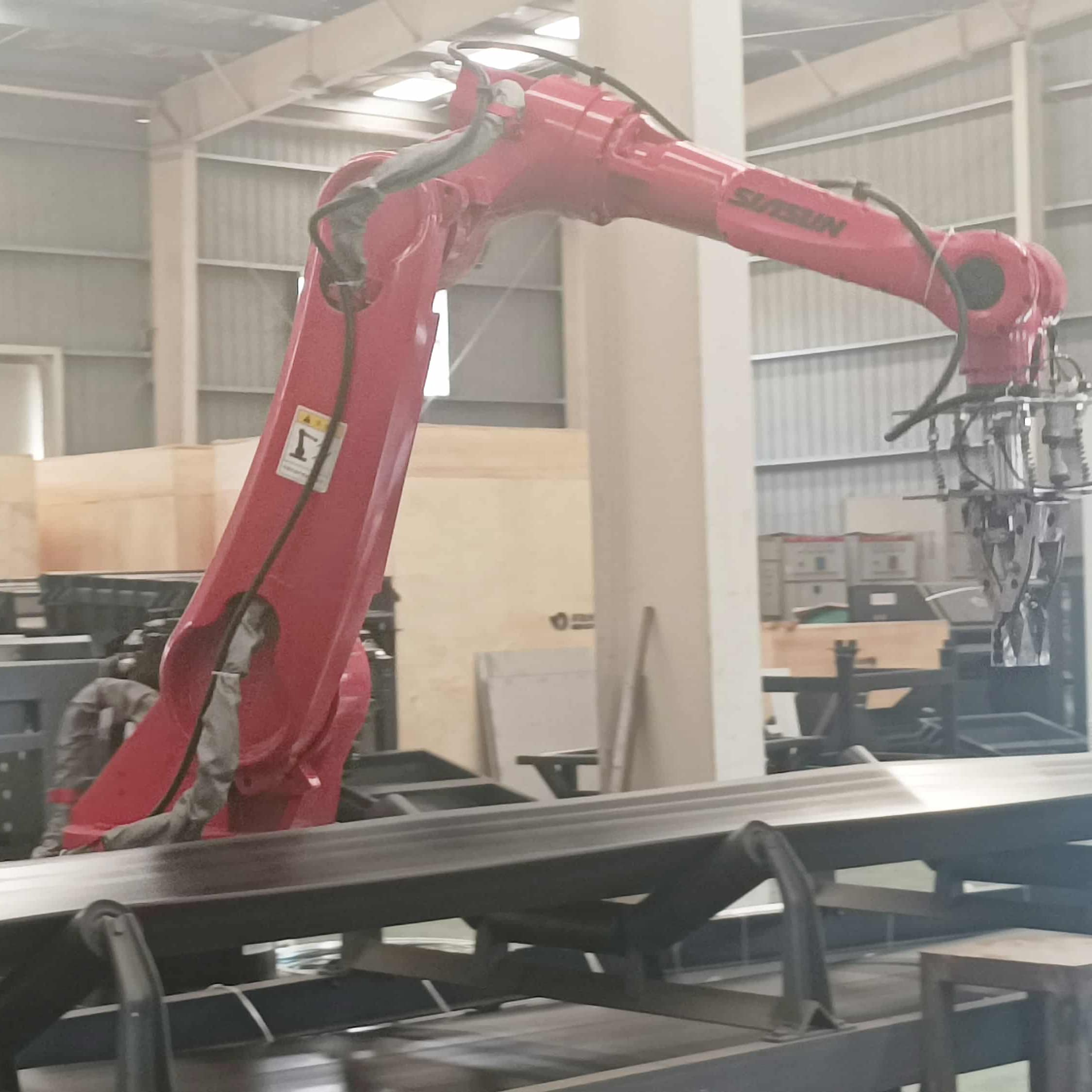
In industrial manufacturing and logistics, various industrial robots can be used to optimize the flow of goods, and one of the common applications is the depalletization of materials. "Robotic depalletization" usually refers to the process of sequential unloading of materials from pallets using robotic arms and can be used to replace simple but heavy manual labor. In logistics, there are scenarios where goods of different gauges (i.e., different sizes, weights, or textures) are delivered in boxes, as shown in Figure 1.
However, early robotic depalletizing systems were mainly controlled manually to complete robot gripping, which was only applicable to the unloading of a single cargo and required the cargo to be arranged in a fixed order, and the robot did not have the perception capability to react to external changes. However, multi-gauge material depalletization systems require robots to have real-time environmental awareness to guide the gripping action because the objects to be unloaded are variable in size and irregularly placed.
With the development of various optical sensors, computer vision technology has been gradually introduced into robot grasping tasks to improve the robot's ability to acquire external information. A vision-guided robot depalletizing system usually contains five modules, which are vision information acquisition module, object localization and analysis module, grasping position calculation module, hand-eye coordinate conversion module, and motion planning module, as shown in Figure 2. Among them, the first three modules are the main part of the vision system, responsible for acquiring and processing visual information and providing object poses. The last two modules are mainly used to provide control information to the robot and complete the grasping function. In the following, we will introduce each module, common methods and implementation cases.
I. Vision information acquisition module
The role of the vision information acquisition module is to capture visual information and provide input for subsequent steps. At present, the commonly used visual inputs include 2D RGB images, 3D point cloud images and combined 2D and 3D RGB-D images. Among them, vision-assisted robotic arm grasping based on 2D RGB images is currently a mature solution in industry, which transforms the robot grasping problem into the problem of doing object target detection or image segmentation on RGB images. However, 2D vision lacks absolute scale information of objects and can only be used under specific conditions, such as scenarios with fixed pallets and known material sizes. For scenarios where the material gauge is unknown, the vision module is required to provide the robot with accurate absolute size information of the object to be grasped, so only 3D point cloud images or RGB-D images with a combination of 2D and 3D can be used. Compared with RGB information, RGB-D information contains spatial distance information from the camera to the object; compared with 3D point cloud images, RGB-D information contains rich color texture information. Therefore, RGB-D images can be used as the visual information input of the multi-gauge material depalletizing system.
Object positioning and analysis module
The object positioning and analysis module receives the data input from the vision information acquisition module, analyzes the materials present in the scene, and obtains key information such as their position and pose, and then inputs this key information into the grasping pose calculation module. Generally speaking, the material localization problem in robotic depalletizing system can be transformed into a target detection or image segmentation problem in the vision field. The RGB-D vision-based robot grasping solution can first perform 2D target detection or 2D image segmentation on the RGB image for the material, and then fuse the depth map to output the absolute size of the object and the grasping pose; or directly do target detection or segmentation on the 3D point cloud map. The following will be a brief introduction to the related work.
1.2D target detection
The input of 2D target detection is the RGB image of the scene, and the output is the class and position of the object in the image, and the position is given in the form of border or center. The methods for target detection can be divided into traditional methods and deep learning based methods. Traditional target detection methods generally use a sliding window to traverse the entire image, with each window becoming a candidate region. For each candidate region, features are first extracted using SIFT, HOG and other methods, and then a classifier is trained to classify the extracted features. For example, the classical DPM algorithm uses SVM to classify the modified HOG features to achieve the effect of target detection. The traditional method has two obvious drawbacks: firstly, it is very time-consuming to traverse the whole image with a sliding window, making the algorithm's time complexity high and difficult to apply to large-scale or real-time scenarios; secondly, the features used often need to be designed manually, making such algorithms more experience-dependent and less robust.
2. Two-dimensional image segmentation
Image segmentation can be regarded as a pixel-level image classification task. Depending on the meaning of the segmentation result, image segmentation can be divided into semantic segmentation and instance segmentation. Semantic segmentation classifies each pixel in an image into a corresponding category, while instance segmentation not only performs pixel-level classification, but also differentiates different instances on the basis of specific categories. Relative to the bounding box of target detection, instance segmentation can be accurate to the edges of objects; relative to semantic segmentation, instance segmentation needs to label different individuals of similar objects on the graph. In depalletizing applications, we need to extract the edges of materials precisely to calculate the grasping position, so we need to use instance segmentation techniques. The existing image segmentation techniques can be divided into traditional methods and deep learning based methods.
Most of the traditional image segmentation methods are based on the similarity or mutation of gray values in an image to determine whether pixels belong to the same class. The commonly used methods include graph theory-based methods, clustering-based methods and edge detection-based methods.
Deep learning-based methods have substantially improved the accuracy of 2D image segmentation compared to traditional methods. Typical deep neural network frameworks, such as AlexNet, VGGNet, GoogleNet, etc., add a fully connected layer at the end of the network for feature integration, followed by softmax to determine the category of the whole image. To solve the image segmentation problem, the FCN framework replaces these fully-connected layers with deconvolution layers, making the output of the network from a one-dimensional probability into a matrix with the same resolution as the input, which is the pioneering work of applying deep learning to semantic segmentation.
3. 3D target detection
3D target detection enables robots to accurately predict and plan their behavior and paths by directly computing the 3D position of objects to avoid collisions and violations. 3D target detection is divided into monocular camera, binocular camera, multiocular camera, line surface LIDAR scan, depth camera and infrared camera target detection according to the type of sensor. In general, stereo/multi-vision systems consisting of multi-vision cameras or LiDAR enable more accurate 3D point cloud measurements, where multi-view-based methods can use parallax from images of different views to obtain depth maps; point cloud-based methods obtain target information from point clouds. In comparison, since the depth data of points can be measured directly, the point cloud-based 3D target detection is essentially a 3D point delineation problem and is therefore more intuitive and accurate.
Third, the capture pose calculation module
The gripping posture calculation module uses the position posture information of the target object output from the second module to calculate the gripping posture of the robot. Since there are often multiple graspable targets in a multi-gauge material depalletizing system, this module should solve the two problems of "which one to grasp" and "how to grasp".
The first step is to solve the "which" problem. The goal of this problem is to select the best crawl target among many crawl targets, and the "best" here often needs to be defined by the actual requirements. Specifically, we can quantify some indicators that have an impact on the crawling judgment according to the actual situation, and then prioritize these indicators.
The second step is to solve the problem of "how to catch". We can choose to analyze and calculate the grasping posture by mechanical analysis, or we can first classify the object by learning method, and then select the grasping point according to the classification, or directly regress the grasping posture.
Fourth, the hand-eye coordinate conversion module
With the third module, we have obtained a feasible gripping pose. However, the gripping pose is based on the pose in the camera coordinate system, and the gripping pose needs to be converted to the robot coordinate system before motion planning can be performed. In depalletizing systems, hand-eye calibration is usually used to solve this problem. Depending on the camera fixation position, the hand-eye calibration method can be divided into two cases. One is that the camera is fixed on the robot arm and the camera moves together with the arm, called Eye-in-hand, as shown in Figure 3. In this relationship, the position relationship between the robot base and the calibration plate remains constant during the two movements of the robot arm, and the solved quantity is the position relationship between the camera and the robot end coordinate system. The other type of camera is fixed on a separate stand, called Eye-to-hand, as shown in Figure 4. In this case, the attitude relationship between the end of the robot and the calibration plate remains the same during the two movements of the arm, and the solution is the attitude relationship between the camera and the coordinate system of the robot base. Both cases are eventually transformed into a solution problem with AX=XB, and the equation can be transformed into a linear equation using Lie group and Lie algebra to solve for the rotation and translation quantities, respectively.
Fifth. Motion planning module
This module mainly considers the kinematics, dynamics, mechanical analysis, and motion planning of the robot to plan a feasible motion path that does not collide with the environment. By multiplying the grasping pose in the camera coordinate system obtained by the grasping pose calculation module with the conversion matrix calibrated by the hand-eye coordinate conversion module, we can get the grasping pose in the robot arm coordinate system. Based on this posture, the motion planning can be carried out and the robot arm can be guided to complete the depalletizing task. Therefore, the input of the motion planning module is the starting and target positions of the robot arm, and the output is the motion path of the robot arm.
The complete motion planning algorithm can be split into the following three steps.
Step 1: Inverse kinematic solving. In order to avoid problems such as singularities, robotic arm motion planning is generally performed under joint space. Therefore, we should first perform the inverse kinematic solution based on the input poses to obtain the joint values corresponding to the poses.
Step 2: Path planning. With the path planning algorithm, we can get the motion path of the robotic arm. The goal of this step is twofold: one is obstacle avoidance, to ensure that the robotic arm does not collide with other objects in the scene during its movement; the second is to improve the operation speed in order to increase the operation efficiency of the system. By planning a reasonable motion path, the running time of a single grasp of the robotic arm can be made shorter, thus improving efficiency.
Step 3: Time interpolation. Although we can already get a feasible motion path through path planning, however, this path is composed of one location point after another. When the robot arm is running along this path, it needs to keep acceleration and deceleration, so it will have an impact on the running speed. For this reason, we need to perform temporal interpolation to obtain the velocity, acceleration, and time information for each point on the path as the robot arm moves to that point. In this way, the robot arm can run continuously and smoothly, thus improving efficiency.
Sixth. Implementation Example
Based on the above research, a complete vision system consisting of 3D depth camera, lighting system, computer, and vision processing software can be used in the piece box material identification scenario to obtain some special information about real objects, and the information obtained through this system can be used to accomplish some special tasks, such as obtaining the box position through the vision system, which can guide the robot to grasp and obtain the box quantity information as a calibration for the task. The main components of this system, as shown in Figure 5.
The 3D camera and light system are mainly used for photo imaging, where the 3D camera can obtain depth data within a certain range. And the digital image imaging is related to the illumination system. The computer, on the other hand, includes general-purpose computing and storage devices for saving images, processing images through specialized vision software, and also for network communication with other systems. The image display facilitates the operator to operate the vision processing software and monitor the system operation. Large-capacity storage is used for permanent or temporary storage of images or other data. Specialized vision software, on the other hand, includes digital image processing, image data analysis, and some special functions.
Generally speaking, a 3D depth camera has a frame rate of 1 to 30 fps, RGB image resolution of 640×480, 1280×960, special 1920×1080, 2592×1944, and a depth range of about 500mm to about 5000mm.
And depending on the price, there are different precision and range. Here is an example of a brand of 3D camera with parameters as shown in Figure 6 and accuracy as shown in Figure 7.
With the 3D camera, you can get RGB images and depth images of special scenes, and according to the processing and analysis of these images (see Figure 8), you can get some information about the position, number, and information of objects in the scene.
The rectangular box in Figure 9 is the box grabbing position map identified after processing. The order of upper left, lower left, upper right and lower right is "2, 3, 3, 2" respectively, that is, the robot hand will grasp two boxes on the left, three boxes on the left, three boxes on the right and two boxes on the right according to the position information given by the image recognition system.
Seventh. Summary
In this paper, we have introduced the framework and common methods of 3D vision-guided multi-gauge material robot depalletizing system, and defined several basic modules that the framework needs to have, namely, vision information acquisition module, object localization and analysis module, grasping position calculation module, hand-eye coordinate conversion module, and motion planning module, and explained the main tasks and common methods of each module. In practical applications, different methods can be used to implement these modules as needed without affecting the functions of other modules and the system as a whole.


 IPv6 network supported